November 2025
Site levelling
The ground around the windmill has been levelled in readiness for finishing the track which the fan tail runs on
August 2025
Roundhouse displays
The roundhouse has now been made into our main visitor area, with the different bays between the mill's feet containing displays on mills, milling, millers and millwrighting
November 2024
Roundhouse roofing
Secondary rafters and roofing boards (also recovered from the 'site fencing' of a local housing development) have been added
An adjustable jig was used to get the shape of each segment of roof, and transfer it to the boards
The roofing felt was fitted in 36 individually tailored pieces,
with joints capped with rubberised aluminum mesh to give a 'leaded' look
We now have a dry and weatherproof space!
August 2024
Roundhouse roof
Reinforcing the wall plate corners to receive the rafters:
(angle grinder craftsmanship!)
The rafters for the 12-faced 'conical' roof are being cut from fencing rails recovered from the 'site fencing' of a local housing development:
June 2024
Roundhouse
Local builder RedHill Construction has started laying out the reconstruction of the mill's Flemish-bond 12-sided 'roundhouse', which will protect the mill's supporting structure.
The 12 sided construction requires special '150 degree corner bricks' for the outer skin, which they are making on site carefully joining cut bricks with resin (coloured with brick dust to ensure a match)
Quality workmanship!
February 2024
Fanstage
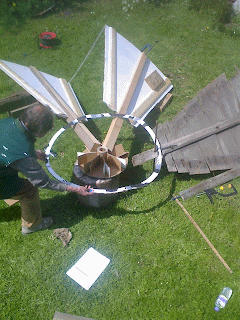
Final assembly of the fan blades into a cast iron hub (the blades were made quite a while back, copies of a single surviving blade- see also August 2014 entry!)
Unlike other mills, where the blades sit in an angled slot cut in 'flat' spokes, Chinnor has angled spokes which means that mounting spokes onto the cast iron hub is not a trivial piece of geometry,
November 2023
Ladder wheels
One of the surviving ladder wheels had fractured, so we commissioned Didcot Railway Centre to re-weld it and fit a reinforcing metal tyre to strengthen their repair.
and the wheels in their wooden bearing housings fit up onto it:
August 2023
Test assembly of the fan stage drive system (gears are wooden patterns- yet to be cast)
June 2023
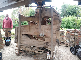
Stripping down and refurbishing the Winnower (see separate page), lots of rusted up parts to free up (soaked in vinegar plus appropriate sized hammers) and some replacement 'pre-aged wood' paneling grafted into the casing
March 2023
February 2023
December 2022
Making up a pair of 'mock' stones (from wooden decking), for an exhibit to help visitors to understand how the stones are supported, and how the gap between them is adjusted:
(See also the operation section of the 'illustrations' page)
November 2022
Flour dresser sieve shells now completed:
Two nested feed hoppers tucked into the roof profile
In its auxiliary 'smutter' configuration the dresser has a slightly inclined cloth-covered shell which is used to clean dirty grains prior to milling:
In its second, more normal configuration as a 'flour dresser' we'll feed freshly ground wholemeal flour down a more steeply inclined tubular wire mesh sieve, separating the white flour from the bran and sending them down different exit chutes (see Jan 22 update)
August 2022
Collected two custom hardwood windows for the roundhouse, made for us by supporter Alun Howell in South Wales
July 2022
Test assembly of the first batch of flour dresser components
June 2022
Production of the 64 'quarter arcs' needed for the flour dresser sieve support frames:
whilst also allow us to clamp sets of arcs together for cutting the longeron rebates
The plan is that all those rebates line up...Wallower gear teeth pegged in place and the gear is re-assembled around its drive shaft:
April 2022
Making up the frame for our replica flour dresser:
Two ash end frames are made up, with a bolt in each corner:
and then they hold captive the long front and back beams, with round-ended pegged tie beams between the end frames to hold it all tight (yet to be fitted .. see photo of the original flour dresser before the mills demolition in the 1960's).
(See also Nov 21 update below)
March 2022
Setting up for 'mass production' of the 64 quarter-circle arcs needed to make up the upper and lower flour dresser sieve frames
Use a jig and router to precisely cut the locating/joining slots in the arc ends:
And you have your initial test rings
Test run complete! just 64 more proper ones to make now.
February 2022
Making and fitting the spouts down from the dresser exit chutes:
January 2022
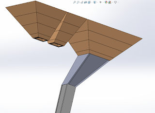
Making up the converging section for the first dresser exit chute, piece shapes calculated in CAD, tested in cardboard and then made using floor boards:
December 2021
Making up various two-part 'core patterns' to create temporary sand shapes which, when combined with wooden gear 'patterns' will give square drive holes in the resultant iron castings:
The version shown here will create a square hole with 4 wedge slots to allow centralisation of the flour dresser brush frame (see November update)

For the bevel gears used in the fan tail drive mechanism we need two versions of these cores for each gear as the same gear forms will be mounted onto different sized shafts:
November 2021
Bent up some 'tentering linkage' (see illustrations page) components at Coombe mill's forge...
...copying cardboard templates
Chinnor's flour dresser, a rotary sieve which would have separated the bran from freshly milled flour to give white flour, was saved during the demolition, and has ended up at Pitstone windmill nearby.
We have taken detailed measurements from it, and are now building a replica, together with its flour feeder:
The first stage has been to make the exit chutes and lift them up into a frame mounted under the floor joists:
We are also making a second vibratory feeder which appeared in a photo at the time of demolition, which we believe made possible an alternative grain feed into the dresser, enabling it to be used as a 'smutter' to scrub the grain prior to milling:
October 2021
We've repainted the mill's workshop, planted a small box hedge along its front, and cleared spiders webs from all the security cameras!
September 2021
We have repainted the mill:
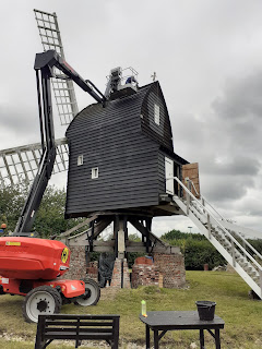
We hired a Manitou 160 all-terrain 'boom lift' for a week, to provide flexible access around the mill with three of us working in shifts to apply 2 coats (over 100kg) of Bedec 'Barn paint'
Watch that paint dry!
and took the opportunity to finish terminating the lightning conductors which run down from the sail tips and which are now bonded onto the windshaft (and from there through the mill down to Earth).
The roof ridge is 11metres above ground, and the sail tips are considerably higher...this was not a task for those with vertigo....
May 2021
After mocking up the wallower gear's 82 degree mesh with the much larger 'brake wheel'...
...the final shaping of the wallower teeth was achieved...
April 2021
Grain hopper ducting from the grain bin on upper floor, down to above the stone's feed hopper:
March 2021
'High Tech'
Updating the CAD model, to allow the creation of animations of the windmill's mechanism (see illustrations page):
(See also 'construction' and images' pages- CAD work courtesy of Craftytech.co.uk and their 'vintage machinery documentation service'- see Links)
The variable angle mechanism for the feed chute has been made and fitted:
The feed shoe is pivoted at its higher end (so it can be shaken as the stones turn to help the grains flow), and the lower end can be raised or lowered by a winding a cord, to change the rate of flow:
The bell tilts over once its restraining strap within the hopper becomes exposed, so allowing the bell to ring, alerting the miller that they must top it up from the grain bins on the floor above.
February 2021
'Low tech'
Making cardboard templates for the grain bins on the upper floor :
Also installing the take-off drive and its actuation lever to lower it into engagement with a horizontal auxiliary gear (shown mocked up in cardboard) to provide a belt drive to the flour dresser which will be positioned at the rear of the mill:
The original auxiliary gear is in a very poor state,
And of course we are preparing the mill for visitors in the near future!
November 2020
Locked down again, so a quiet workshop, but doing 'homework' on gear teeth blanks for the new wallower, sliding gates for the feed hoppers, and chutes directing the flour from the edge of the stones into a sack
October 2020
Testing a flemish bond brick layout for the corners of the 12 sided roundhouse, single thickness alongside the piers, double thickness for doors and windows:
July 2020
Back at work following the COVID19 lockdown, working on the wallower gear teeth and turning up some spindles for the feed hoppers:
April 2020
The windmill is in 'self-isolation', all day
March 2020
Wallower gear blank put in place to allow measurement of the geometry needed to derive the brake and wallower gear tooth profiles:
'Brake floor' and LED lighting added to improve accessibility for working on the brake wheel teeth:
December 2019
Dismantling the old 'wallower' gear to discover how its unique design was implemented.
3 segments are assembled as a 'U' around the drive shaft and then the final segment is held in place by iron bands, in this way the gear can be fitted around already installed shafts.
We are now making a new version from oak, slightly smaller to match the brake wheel position we've ended up with.
(You may also be able to spot the miniature '1mm to the inch' version we had laser cut from basswood to check out the design.)
May 2019
Forging the angled rod ends for the 4 fan tail tie rods at the 'Hot metal works' at the Museum of Water and Steam in Kew.
We've got the ends, now for the middles...
March 2019
Fitting the control ropes and pulleys to the brake mechanism.
The brake lever is the slightly lighter angled beam (which is pivoted at the front of the mill- to the left in the photo).
Its weight applies the pressure around the brake band, and the rope and pulley are to lift it clear when you want the sails to turn.
You can also see the special hook which allows you to latch the brake up, but also release it with a sharp tug on the control rope.
February 2019
The hopper construction is 'furniture grade' carpentry!
Turning up the first set of legs for the grain feeding hoppers.
A new top bearing segment is now seated correctly on the rear of the windshaft. This is not an original feature but it will provide a safety restraint should the mill ever become 'tail-winded', and addressees the somewhat front-heavy sail layout, resulting from a relatively short windshaft.
The brake band has been dismantled in the workshop and lifted into the mill in segments and reassembled in position around the brake wheel. The mounting chains and brackets to hold it clear, and the brake lever to apply it ,will follow shortly.
Then, once we know we can stop the mill, we can move to turning the sails using the wind.
Work on a weight-powered door closing system for the workshop, to help keep in any heat!
January 2018
Final assembly of the new brake band, demonstrating that volunteers can do it!
On cleaning up the the original brake band irons, we've found stamped text suggesting they were made at Coalbrookdale:
September 2017
The replacement brake is being assembled- we have the original, but after close examination we decided that 'new copy' rather than 'restoration' was appropriate for such a safety-critical item
August 2017
Fitting the tooth blanks into the brake wheel. They have 1/4" taper on two sides of their shank to lock them in position, plus a complex tooth form which will be dressed 'in situ'
March 2017
Now the old shed has been removed there's space for the foundations for the remainder of the fan tail track to be dug:
They seem quite deep though!
October 2016
The Chinnor Historical and Archaeological Society have made a donation to help cover the costs of manufacturing the cast iron wheels, gears and bearing housings needed to complete the fan tail mechanism.
The C H A S logo will be incorporated into the patterns for these casting, providing a permanent record of their support to the windmill and their role in the village.
September 2016
Lifting the new windshaft tail beam on up to the upper floor, and lowering the badly rotten beam which it replaces - two 1000kg chain hoists, 4 people, 5 hours.
August 2016
It's basic carpentry, it's just that the pieces are massive and so handling them takes time.
Here we are lifting a new windshaft tail beam up the steps into the mill.
Next time we'll lift it to the upper floor and into position, and lower the old rotten piece.
June 2016
Dismantling and clearance of the old iron shed.
We've made a raised bed in its place so we can grow some wheat for grain-to-loaf events (some time in the future)
The old iron shed is flat packed again for one last relocation.
5 page article in Landscape Magazine (March/ April edition from page 88) on the mill's restoration
Featured on BBC2's 'Escape to the country- Oxfordshire' as a reason to move to Kingston Blount
January 2016
The move into the new visitor center/workshop is now almost complete.
The the rusty old corrugated iron shed (which was at least third-hand when it was re-erected in 1982), which had kept off the worst of the weather while we made the replacement parts for the mill, is now cleared, ready for demolition.
December 2015
The sail are being moved forwards slightly and re-angled to improve clearance on the front left of the mill.
August 2015
In the grinding area the stone floor has been laid and the casings that surround the stones have been made
- but we are one set of mill stones short.... any offers?
February 2015
We've had the trench dug for the track on which the windmill fan tail wheels will run (using digger- not by hand!). This will be filled with hardcore and will also contain a drainage pipe to help prevent the mill base filling with water after heavy rain.
January 2015
The fitting out of the visitor centre with lighting, electrics and workbenches is complete, so you can now look around a permanent display on the mill's history and restoration, and we can work in the dry and out of the wind!
(bring your own coffee and sandwiches!)
December 2014
The hay rake wheels had previously considering using for the fan tail carriage (see June 2013 entry) have proved too lightweight, so we have bought a pair of heavyweight wheels, originally used on a traction engine's water bowser in Cornwall:
In order to fit the worm ring gear onto this 10 spoked wheel, the pattern has been converted from 6 to 5 spokes:
November 2014
Taking a break from fitting out the visitors centre
October 2014
A link to video of the sails being lifted into place is now under 'other websites'
Chinnor windmill now has sails again, 47 years after it was completely demolished, (seen here being turned by hand from inside!)
The volunteers have put in over 15,000 hours of work to get the windmill to this stage.
Lifting the sails in practice...(It went pretty much according to the plan below!)


September 2014 ...planning!
Lift sail number 1 (with the mill's 'parking brake' full on), then ASAP put number 3 on to balance things up again.
Breathe a sigh of relief, have a brew up, then release the brake and turn the sails a quarter turn.
Repeat with sails 2 & 4, then go home after a good days work!
September 1st 2014
The sails are now on site
August 2014
Test assembly of the fan tail blades onto their cast iron hub
July and August 2014
The 'visitor centre' is built up on the stone floor and foundation wall of a cowshed recovered from Milton Common.
Part of the building will form an exhibition area for artefacts from the mill and and displays on the mills history and restoration, and part will act as a workshop in which the remaining mill machinery can be rebuilt.
23rd July 2014
The sails are being made for us by Dave Empringham and his team of millwrights, weather permitting we hope to fit them on the 16th -17th September
The sails will be fitted with canvas to start with, but have been designed for easy conversion to fit the surviving patent shutters, as and when funding allows!
July 2014 'Homework'
Scarf jointing an angled hidden dovetail joint onto one of the diagonal braces which support the fantail frame
13 April 2014
Fantail frame assembly lifted into place
31st March 2014
The fantail frame (built in the shed during the winter) is reassembled outdoors ready for lifting into position
27th October 2013
Tail pole fitted (laminated Siberian larch), and the stocks prepared ready for lifting into place
1st June 2013
Checking templates for the reconstruction of fan tail (from the one surviving blade):
and making patterns for the various cast iron gears required, a left handed worm wheel set to drive the fan stage wheels...
and a 3:1 bevel gear set for transmitting the fan drive down to the wheels
17th April 2013
Windshaft is lifted onto its bearings and the brakewheel wedged in place onto the windshaft
2nd Nov 2012
Featured in the Thame Gazette as we lifted in the auxiliary drive gear
July 2012
Working on the central strengthening stringer up the middle of the steps (using a two man saw)
National Mills Day 2012 (second Sunday in May)
Along with most other mills across the country, Chinnor mill was open to the public, with tours round the mill in the afternoon, explaining the mill's history, operation and restoration.
4/3/2012
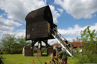
The new steps have now been lifted up to provide access to the mill. This will make it easier to admit visitors safely without needing to climb a ladder as that had been the only way to access the mill since it was lifted onto the main post last summer.
23/2/2012
Following the lift of the buck house onto the trestle earlier in the summer, work is ongoing to construct the permanent steps up into the back of the mill. This will soon provide access for visitors and make working on the mill easier too!
The volunteer team works on the mill mostly on alternate Sunday mornings. Please drop along and visit, or volunteer to help.
There is a link to a short video of the buck being lifted onto its post
listed under 'other web sites'


.jpg)


.jpg)


.jpg)




.jpg)


.jpg)


